
🔧 Troubleshooting Injection Molding #8 – Splays or Silver Streaks
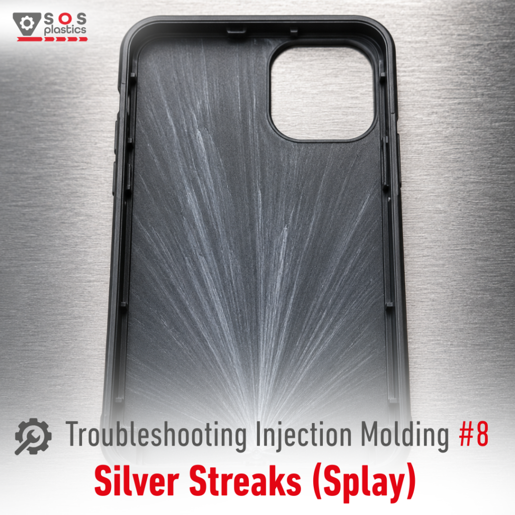
Splays (Silver Streaks) – silvery streaks visible in the flow direction, caused by gas being stretched through the melt during filling. When troubleshooting Splays, investigate the causes in the right order: 1️⃣ Moisture in the material (most common root cause)➡ Verify actual moisture content (use moisture analyzer if possible), drying time, drying temperature and dryer performance. Do NOT overdry! 2️⃣ Melt degradation➡ Measure the actual melt temperature (use pyrometer or contact thermometer). Reduce melt temperature or residence time if necessary. 3️⃣ Excessive shear➡ Reduce local overheating by checking injection speed, gate size, runners and nozzle geometry. 4️⃣ Air introduced during plasticizing➡ Verify screw recovery speed, back pressure, decompression and check valve condition. 5️⃣ Poor venting➡ Inspect vents, air traps and filling pattern. Improve venting where required. ⚠️ Drying also non-hygroscopic materials may be required when condensation on the surface is suspected. ⚠️ If Splays appear over the entire part, moisture or degradation is usually the first suspect. ⚠️ If they appear only near the gate, excessive shear is often the root cause. Next in the Plastic Troubleshooting Series:➡ Color Streaks – Bad Color Dispersion What is the most common cause of Splays or Silver Streaks in your process?
🔧 Troubleshooting Injection Molding #7 – Black Specks
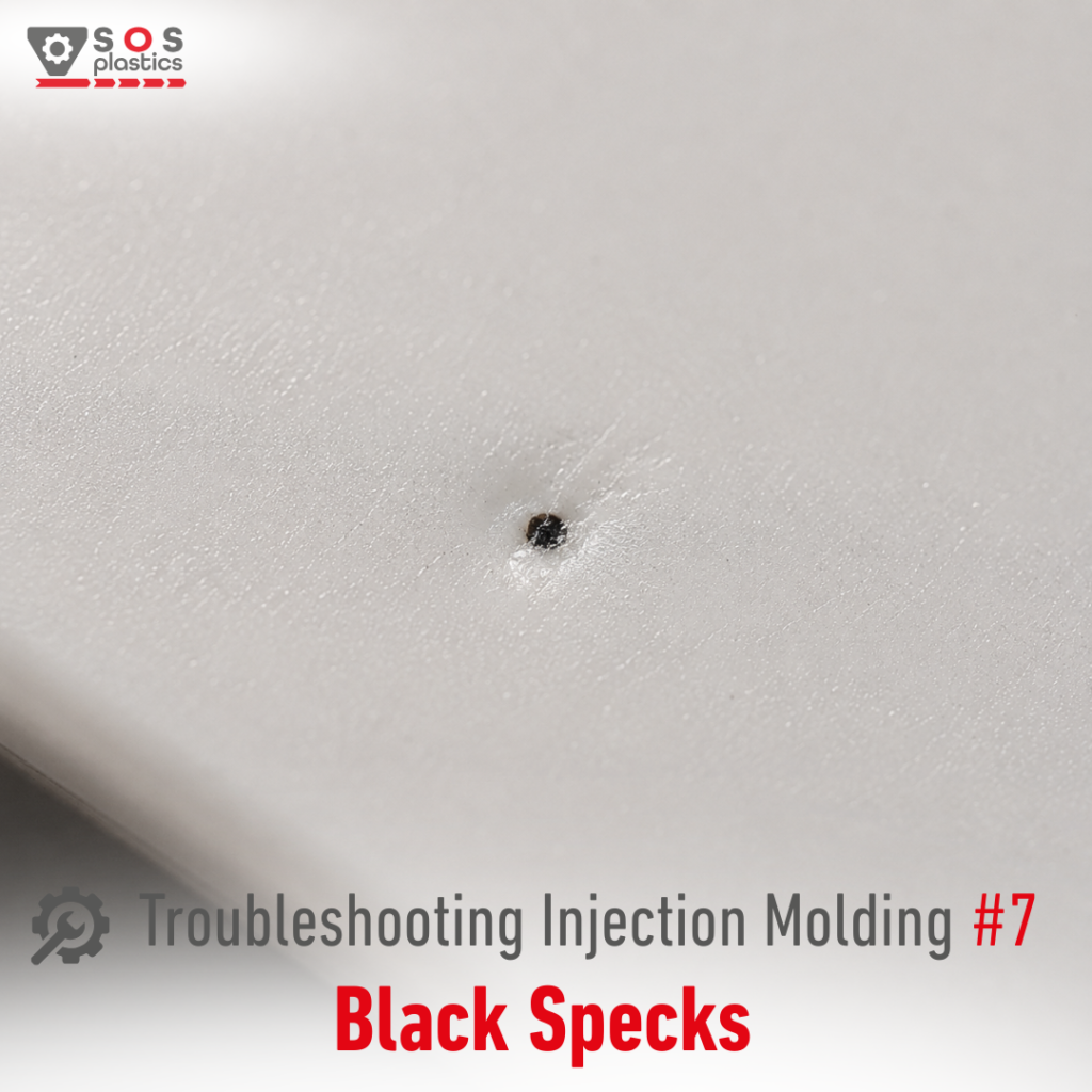
Black Specks are one of the most frustrating cosmetic defects in injection molding. They are small black particles or burnt polymer fragments (or other contamination) visible on the surface or inside the molded part. When troubleshooting Black Specks, investigate the causes in the following order: 1️⃣ Contaminated virgin material or regrind➡ Inspect virgin resin and regrind before processing. Eliminate contaminated batches and verify that regrind handling prevents dirt, dust or foreign particles from entering the process. 2️⃣ Thermal degradation inside the barrel, nozzle or non-return valve➡ Measure the actual melt temperature with a pyrometer.⚠️ If degradation is confirmed proceed like with Burn Marks (Check out other article 🔧 Troubleshooting Injection Molding #5 – Burn Marks) 3️⃣ Thermal degradation inside the hot runner➡ If the melt leaving the barrel is clean, inspect the hot runner. 4️⃣ Poorly cleaned plasticizing unit after other material or color change➡ Carbonized residue from previous production can detach hours after a changeover.Dark colored materials, especially black and brown compounds, are particularly difficult to remove completely before switching to white, natural or transparent materials. Even tiny residues can appear later as Black Specks. ⚠️ Whenever production allows it, dedicate machines or complete material handling lines to white, natural or transparent products. This significantly reduces the risk of cosmetic contamination and improves process stability. 5️⃣ Environmental contamination➡ Not every Black Speck originates inside the machine.Dust and airborne particles from the production environment can enter the material hopper and later become visible on the molded part.⚠️ Whenever possible, use closed automatic material feeding systems to minimize contamination. If this is not available, keep hopper lids closed whenever material is not being loaded. ⚠️ Black Specks often appear intermittently.If the defect disappears for several cycles and then suddenly returns, suspect material hold-up somewhere in the plasticizing system rather than contamination of every shot. ⚠️ For Class-A surfaces, prevention is usually far more effective than troubleshooting. Dedicated equipment, good housekeeping and clean material handling systems eliminate many contamination sources before they ever reach the molding machine. Next in the Plastic Troubleshooting Series:➡ Silver Streaks (Splay) Which methods do you use to prevent from Black Specks in your production?
🔧 Troubleshooting Injection Molding #6 – Diesel Effect

I think my personal best and most interesting subject. Not always easy to investigate and quite hard to deal with. So, what is Diesel Effect?Diesel Effect occurs when air becomes trapped inside the mold cavity during filling. As the melt front advances, the trapped air is compressed into an increasingly smaller volume. Just like in a diesel engine, rapid compression dramatically raises the air temperature, which can become high enough to scorch or even carbonize the polymer. The result is typically:❌ black or dark brown burn marks,❌ carbonized material,❌ degraded polymer,❌ unpleasant burnt odor,❌ and in severe cases, weakened mechanical properties. When troubleshooting Diesel Effect, it is important to investigate the causes in the right order: 1️⃣ Insufficient mold venting (Most Common Cause)If trapped air cannot leave the cavity, pressure rises rapidly until the air reaches ignition temperatures.➜ Clean existing vents, inspect vent depth and add venting where air is trapped. Consider adding additional vents or vent pins in the last-to-fill areas. 2️⃣ Injection speed too highHigh filling speed compresses trapped air much faster, increasing the temperature before the air has time to escape.➜ Reduce first stage injection speed or apply a filling profile that allows air to escape before it is compressed.➜Compare the burn severity before and after reducing speed.If the defect improves immediately, trapped air is very likely the root cause. 3️⃣ Air traps created by part geometryDeep ribs, blind pockets, sharp corners and enclosed sections naturally trap air.Even a perfectly vented mold cannot always evacuate air from a poor part design.➜ Review the filling pattern.➜ Use Moldflow or similar simulation to identify air traps.➜ Modify wall transitions or add venting opportunities if redesign is possible. 4️⃣ Gate location forces air into Dead ZonesSometimes the process is correct, but the melt flow pushes air directly into an area where it cannot escape.➜ Evaluate gate position.➜ Consider relocating the gate or adding secondary gates.➜ Optimize the filling pattern to move trapped air toward existing vents. 5️⃣ Material Degradation (Secondary Cause)Not every burn mark is Diesel Effect.If discoloration appears randomly rather than consistently at the last-to-fill location, excessive residence time, high melt temperature or thermal degradation inside the barrel may be responsible.➜ Verify residence time.➜ Check barrel temperature profile.➜ Inspect screw recovery and back pressure.➜ Confirm that the material is not degrading before entering the mold. Next in the Plastic Troubleshooting Series:➜ Black Specks Have you ever solved a Diesel Effect issue by improving venting instead of changing processing parameters? Share your experience in the comments.
🔧 Troubleshooting Injection Molding #5 – Burn Marks
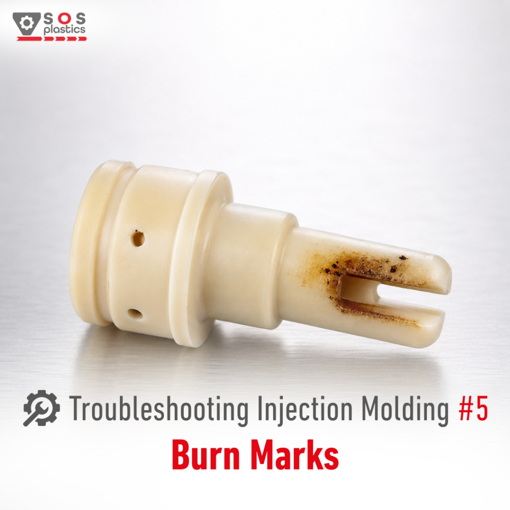
Another very common problem often present during IM are Burn Marks. There are 2 fundamental causes of Burn Marks. In this article I will cover the first one related with Thermal Degradation. Second reason is called Diesel Effect and will be discussed later on. As always we can proceed to troubleshooting ONLY once fundamentals are verified. Burn Marks are brown, dark brown or black discoloration, dark streaks, or degradation visible on the surface of the molded part. When troubleshooting Burn Marks, it is important to investigate the causes in the right order: 1️⃣ Thermal degradation in the barrel or nozzle➡ Verify the actual melt temperature using a pyrometer (or contact thermometer).➡ Reduce melt temperature if possible.➡ Check heater bands and thermocouples for proper operation.➡ Reduce screw RPM and/or back pressure to minimize frictional heating.➡ Check material residence time in the barrel.➡ Inspect and clean the screw if deposits are present.➡ If using a shut-off nozzle, consider switching to an open nozzle if appropriate. 2️⃣ Thermal degradation in the hot runner➡ Verify manifold and nozzle temperatures.➡ Reduce hot runner temperatures if possible.➡ Inspect the hot runner for material stagnation or hold-up areas. ⚠️ The order above follows one of the classic troubleshooting references for injection molding and focuses primarily on thermal degradation inside the plasticizing unit and hot runner. ⚠️ However, many experienced processors know that Burn Marks are often associated with trapped air and the Diesel Effect rather than thermal degradation alone. We’ll cover the Diesel Effect in the next Plastic Troubleshooting article and explain why compressed air can locally burn the polymer even when the melt temperature is perfectly correct. Next in the Plastic Troubleshooting Series:➡ Diesel Effect – The Hidden Cause of Burn Marks Have you ever solved Burn Marks by reducing melt temperature, or was the real culprit trapped air inside the mold?
🔧 Troubleshooting Injection Molding #4 – Voids

Voids are one of the best examples of defects that may not be visible at all. A part can look perfectly acceptable externally while containing internal cavities that reduce strength and long term performance. Just like Sink Marks, Voids are typically related to shrinkage and insufficient packing. Understanding Fill Ratio and proper packing behavior is often the key to finding the root cause. Voids – when internal cavities or pores form inside the molded part.When troubleshooting Voids, it is important to investigate the causes in the right order:1️⃣ Holding pressure too low➡ Increase holding pressure and verify that sufficient material is packed into the cavity during cooling. 2️⃣ Holding pressure time too short➡ Increase holding pressure time and determine the actual gate freeze time. 3️⃣ Incorrect V/P transfer (holding pressure switch-over point)➡ Adjust the transfer point and verify cushion consistency shot-to-shot. 4️⃣ Injection speed too high➡ Reduce injection speed and evaluate whether packing stability improves. 5️⃣ Melt temperature too high➡ Reduce melt temperature and verify the actual melt temperature with a pyrometer. 6️⃣ Faulty non-return valve (check ring leakage)➡ Check cushion repeatability and replace the valve if leakage is suspected. 7️⃣ Back pressure too low➡ Increase back pressure carefully to improve melt consistency. 8️⃣ Mold or part design issues➡ Review gate location, gate size, runner dimensions, and excessive wall thicknesses. ⚠️ Voids and Sink Marks often share the same root cause. The difference is that Sink Marks are visible on the surface, while Voids remain hidden inside the part. ⚠️ A proper precision scale can be extremely helpful when troubleshooting Voids. Stable part weight is often one of the best indicators that packing conditions are under control. Next in the Plastic Troubleshooting Series:➡ Burn Marks What is the most common cause of Voids in your process?
🔧 Troubleshooting Injection Molding #3 – Sink Marks
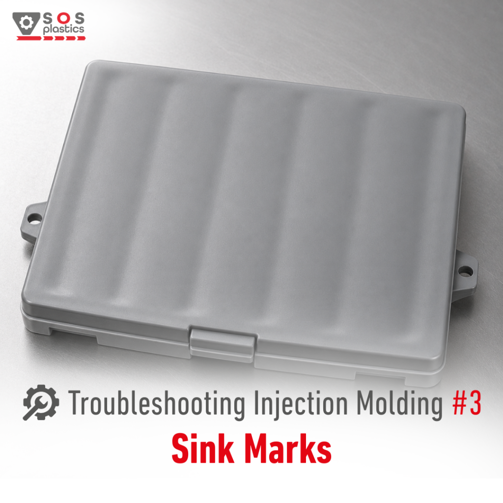
If there is a „holy grail” of injection molding troubleshooting, Sink Marks are probably one of the strongest candidates. Along with Short Shots and Flashes, Sink Marks are among the most common defects encountered in production related with Fill Ratio. A cavity that is not properly filled before transfer to hold pressure will often develop Sink Marks regardless of how much hold pressure is applied later. As always, once the fundamentals are verified, we can move on to troubleshooting. Sink Marks are localized depressions on the surface of a molded part caused by material shrinkage during cooling. When troubleshooting Sink Marks, it is important to investigate the causes in the right order: 1️⃣ Insufficient material volume or faulty non-return valve➡ Verify cushion stability and part weight consistency. Inspect the non-return valve if material loss is suspected. 2️⃣ Holding pressure too low➡ Increase holding pressure and verify whether part weight increases. 3️⃣ Holding pressure time too short➡ Increase hold time and determine actual gate freeze time using a precision scale. 4️⃣ Injection speed too high or too low➡ Optimize injection speed and evaluate cavity filling behavior. 5️⃣ Melt temperature too high➡ Verify actual melt temperature (with contact thermometer!) and reduce it if necessary. 6️⃣ Mold or part design issues➡ Review gate location, gate size, runner dimensions, wall thickness, and rib design. ⚠️ If you suspect insufficient hold time, temporarily set an extremely long hold time (for example 2-3 minutes) as a diagnostic test. If Sink Marks are still present, hold time is not the root cause. If the defect disappears, gradually reduce hold time until you find the shortest setting that still produces acceptable parts. ⚠️ As always, a proper precision scale is one of the most valuable tools for troubleshooting Sink Marks. Next in the Plastic Troubleshooting Series:➡ Voids What is the most common root cause of Sink Marks in your process?
🔧 Troubleshooting Injection Molding #2 – Flashes
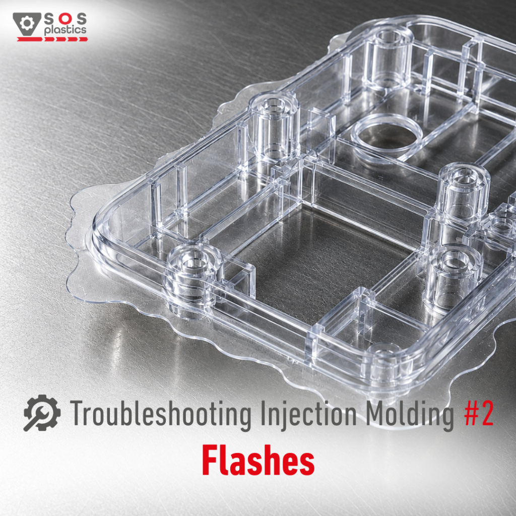
Many processors immediately focus on clamping force when Flash appears.Sometimes that is correct. However, Flash is often another example of why understanding Fill Ratio is so important. Just like with Short Shots, the defect can frequently be traced back to what is happening during filling and packing rather than at the mold parting line itself. Once the fundamentals are verified, we can move on to troubleshooting. Flash – when molten material escapes beyond the intended cavity and appears on the parting line or other mold shut-off surfaces. When troubleshooting Flashes, it is important to investigate the causes in the right order: 1️⃣ Insufficient clamping force➡ Verify clamping pressure settings and confirm that machine tonnage is sufficient for the projected area. Increase clamp force if required. 2️⃣ Injection pressure or holding pressure too high➡ Reduce injection pressure or hold pressure and verify whether excessive cavity pressure is forcing the mold open. 3️⃣ Injection speed too high➡ Reduce injection speed and observe whether cavity pressure and flash formation decrease. 4️⃣ Melt flow too high (material viscosity too low)➡ Reduce melt temperature or mold temperature and verify actual temperatures rather than machine settings alone. 5️⃣ Mold damage, wear, or design issues➡ Inspect parting lines, venting areas, shut-offs, and mold rigidity. Repair worn or damaged tooling where necessary. ⚠️ Before increasing clamp force, verify whether the process is generating unnecessary cavity pressure during filling or packing. ⚠️ Again, a proper precision scale will be extremely helpful when troubleshooting Flashes and evaluating Fill Ratio. Next in the Plastic Troubleshooting Series:➡ Sink Marks What is the most common cause of Flashes in your process?
🔧 Troubleshooting Injection Molding #1 – Short Shots
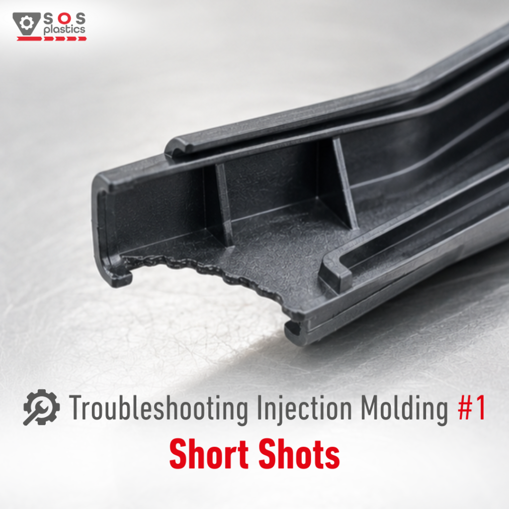
Today I’m launching a new series focused entirely on injection molding troubleshooting. Before we begin, one important note:None of the corrective actions below will deliver reliable results if the fundamentals are not under control.Material must be properly stored, properly dried, processed within the recommended processing window, and protected from overheating or overdrying. Mold temperature must be measured and verified rather than assumed. You can find details about it on my profile in previous posts. Once these fundamentals are in place, we can move on to troubleshooting. Short Shots – when the part is not completely filled. When troubleshooting a Short Shots, it is important to investigate the causes in the right order: 1️⃣ Inadequate shot size (no cushion)➡ Increase shot size and verify material feeding. 2️⃣ Low holding pressure or incorrect V/P transfer (switch over) point➡ Increase the switch over point or holding pressure and verify transfer settings – setting MAX injection pressure may help. 3️⃣ Injection speed too low➡ Increase injection speed to achieve faster filling. 4️⃣ Too long injection time or transfer point setting➡ Adjust fill time and optimize V/P transfer. 5️⃣ Faulty non-return valve➡ Check and replace the valve if necessary. 6️⃣ Insufficient venting➡ Improve venting, clean vents, and verify clamping force (try to reduce it). 7️⃣ Melt flow too low (high viscosity)➡ Increase melt temperature, increase mold temperature, or consider a higher-flow material grade. Use of slip MB may help. ⚠️ The order above matters. In practice, the root cause is often found within the first three points. ⚠️ Getting a proper weight scale will be extremely helpful when dealing with Short Shots. What is the most common reason for Short Shots in your process?
How often do you do that?
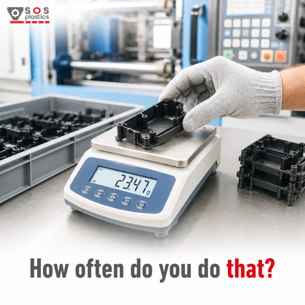
A 0,2g weight change can cost thousands in scrap before anyone notices. Most injection molders look for defects.The best ones look at the scale first.Why? Because part weight is often the earliest sign that a process is drifting.A lighter part can mean:• underpacking• increased shrinkage• dimensional issues A heavier part can mean:• overpacking• flash• excessive internal stress The scary part?The process can drift for hours before defects become visible.That’s why weighing parts remains one of the simplest and most effective process monitoring tools in injection molding. Interestingly, while I frequently see part weight checks during mold trials and process validation runs, I still see them far too rarely during stable serial production. But there’s another catch:Two parts can have exactly the same weight and still have very different quality characteristics. Weight doesn’t tell the whole story but it often tells you first that something is changing. Do you monitor part weight during production, or do you rely on other process indicators?
Case study
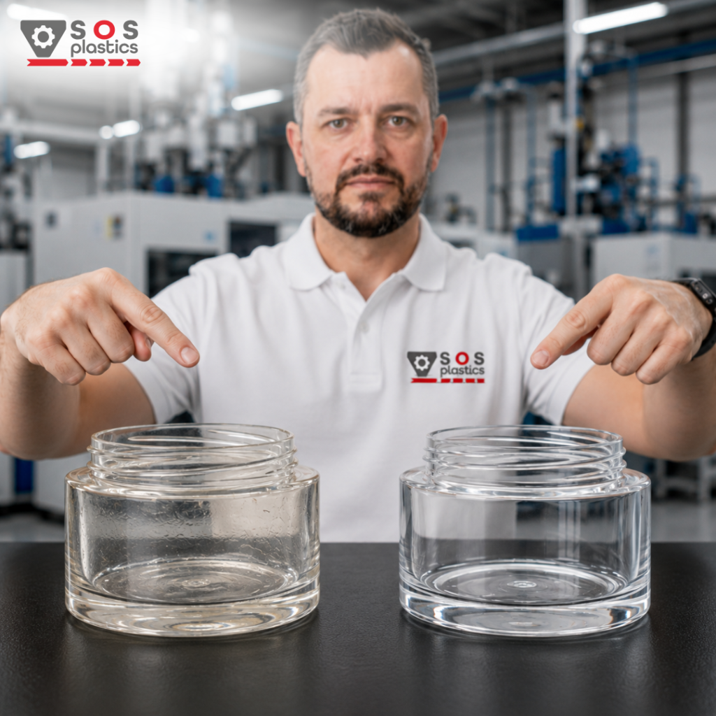
A simple case study showing how important it is to follow basic rules… A few years ago, one of our customers invited me to support a material change project reporting having all different kind of issues with it. The application is a cosmetics container. The goal seemed straightforward: switch from „other material” to PMMA. The reality? A long list of issues appeared immediately after the change:• sink marks• part deformation (warpage)• slight yellowing• unstable process window The yellowing was relatively easy to explain, barrel temperatures were simply set too high. The bigger surprise was the mold temperature.Although the PMMA supplier recommended a mold temperature of 50–70°C for this particular grade, the mold was actually running around 30°C.After increasing the mold temperature to approximately 80–90°C (during the trials this gave best results) and extending cooling time by around 25 seconds, the transformation was immediate:✔ No sink marks✔ No warpage✔ No visual defects✔ Stable production process The project was a good reminder that when changing materials, the resin itself is often blamed first, while the real answer can be hidden in the process settings.Sometimes the difference between a „bad material” and a successful implementation is simply understanding how the new polymer wants to be processed. Let me know in the comment section about your experience with material change fail because of process settings rather than the material itself?